Spin and SpinDup
 | WARNING THIS CONTENT HAS BEEN IMPORTED AUTOMATICALLY FROM 2.0 GUIDE -MIGHT BE OUTDATED AND/OR INACCURATELY CONVERTED |
The spin and spin dup are two other very powerful modeling tools
Spin
The Spin tool in Blender is for creating objects like you can produce with a lathe. Often this tool is therefore called "lathe"-tool or "sweep"-tool in the literature.
First you must create a mesh representing the profile of your object.Ā If you are modeling a hollow object, it is a good idea to give a thickness to the outline.Ā Fig. 1 shows the profile for a wine glass.Ā The file can be found on the CDROM.

With all the vertices selected and in EditMode, access the EditButtons window (F9).Ā The "Degr" button indicates the number of degrees to spin the object (in this case we want a full 360 sweep).Ā The "Steps" button specifies how many profiles there will be in the sweep.

Like Spin Duplicate (covered by the next section), the effects of Spin depend on the placement of the cursor and which window (view) is active.Ā We will be rotating the object around the cursor in the top view.Ā Switch to the top view with KEYPAD_7.Ā The cursor should be placed along the center of the profile.Ā This is easily accomplished by selecting one of the vertices along the center, and snapping the cursor to that location with SHIFT+S>>CURS->SEL.
Fig. 3 shows the wine glass profile from top view, with the cursor correctly positioned.

Before continuing, make a note of the number of vertices in the profile.Ā This information can be found in the Info bar at the top of the Blender interface (Fig. 4)

Click the "Spin" button.Ā If you have more than one window open, the cursor will change to an arrow with a question mark and you will have to click in the window containing the top view before continuing.Ā If you have only window open, the spin will happen immediately.
Fig. 5 shows the result of a successful spin.

Now for the tricky part.Ā The spin operation leaves duplicate vertices along the profile.Ā Unfortunately these duplicates do not always exactly match the original profile.Ā In order to remove them and thereby close the object, we need to take a few steps.
Use the boundary select tool (BKEY) to select all of the vertices that lie along the "seam".Ā The white rectangle in Fig. 6 shows the vertices that must be selected.

Press PERIOD to scale around the location of the cursor.Ā We'll do this to scale the selected points into into a line that passes through the center of the object.
Press SKEY to start scaling.Ā Drag the mouse cursor vertically and press the middle mousebutton.Ā If done correctly, this will constrain scaling operations to the Y axis.Ā If not, you can MIDDLE_CLICK again to turn off the contraint and try again.
While scaling, hold down the CONTROL key to scale in 0.1 unit increments.Ā Scale the line of points down to 0 in the Y axis, and LEFT_CLICK to complete the scaling operation.Ā If you like, you can revert to the default rotation/scaling pivot by pressing COMMA when you have finished.
Remove doubles in the current selection set by pressing WKEY>>REMOVE DOUBLES.Ā A small box will appear saying how many points were removed.Ā Dismiss this box by moving the mouse, pressing ESC or by LEFT_CLICKING or RIGHT_CLICKING.

Notice the selected vertex count before and after the "Remove Doubles" operation (Fig. 8).Ā If all goes well, the final vertex count (38 in this example) should match the number from Fig. 4.Ā If not, some vertices were missed and you will have to go and weld them manually.
 | A tip |
|---|---|
To weld two vertices together, select both of the by holding SHIFT and RIGHT_CLICKING on them.Ā Press SKEY to start scaling and hold down CONTROL while scaling to scale the points down to 0 units in the X,Y and Z axis.Ā LEFT_CLICK to complete the scaling operation and click the "Remove Doubles" button in the EditButtons window. |

All that remains now is to recalculate the normals by selecting all vertices and pressing CONTROL+N>>RECALC NORMALS OUTSIDE.Ā At this point you can leave editmode and apply materials or smoothing, set up some lights, a camera and make a rendering.Ā Fig. 9 shows our wine glass in a finished state.

SpinDup
The Spin Dup tool is a great way to quickly make a series of copies of an object laid out in a circular pattern.Ā The clock.blend file on the CD-ROM contains a clock that is missing the hour marks.

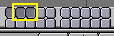
Select the object you wish to rotate (in this example it is the small rectangle at the 12:00 position on the clock, indicated by the arrow in Fig. 1) and switch to the EditButtons window with F9.Ā Set the number of degrees in the "Degr" NumBut to 360.Ā We want to make 12 copies of our object, so set the "Steps" to 12 (Fig. 2).

Switch the view to the one in which you wish to rotate the object by using the keypad. Note that the result of the "Spin Dup" command depends on the view you are using when you press the button.
Position the cursor at the center of rotation.Ā The objects will be rotated around this point.
Select the object you wish to duplicate and enter editmode with TAB.
In editmode, select the vertices you want to duplicate (note that you can select all vertices with AKEY or all of the vertices linked to the point under the cursor with LKEY).Ā See Fig. 3.
| A Tip |
|---|---|
If you want to place the cursor at the precise location of an existing object or vertex, select the object or vertex, and press SHIFT+S>>CURS->SEL. |

Press the Spin Dup button.Ā If you have more than one 3dWindow open, you will notice the mouse cursor change to an arrow with a question mark.Ā Click in the window in which you want to do your rotation.Ā In this case, we want to use the front window (Fig. 4).
If the view you want is not visible, you can dismiss the arrow/question mark with ESC until you can switch a window to the appropriate view with the keypad

When spin-duplicating an object 360 degrees, a duplicate object is placed at the same location of the first object, producing duplicate geometry.Ā You will notice that after clicking the "Spin Dup" button, the original geometry remains selected.Ā To delete it, simply press XKEY>>VERTICES.Ā The source object is deleted, but the duplicated version beneath it remains (Fig. 5).

The clock.blend file on the CD-ROM contains the rest of the clock details and lighting on layers two and three (Fig. 6).Ā Fig. 7 shows the final rendering of the clock.