The 3DWindow

3D Toolbar
Full Window
Maximise the window, or return it to its original size; return to the old screen setting (CTRL-UPARROW).
Layers buttons
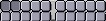
These 20 buttons show the available layers. In fact, a layer is nothing more than a visibility flag. This is an extremely efficient method for testing Object visibility. This allows the user to divide the work functionally.
For example: Cameras in layer 1, temporary Objects in layer 20, lamps in layers 1, 2, 3, 4 and 5, etc. All hotkey commands and tools in Blender take the layers into account. Objects in 'hidden' layers are treated as unselected.
Use LMB for selecting, SHIFT-LMB for adding/removing to/from the group of selected layers.
Hotkeys: 1KEY , 2KEY , etc. 0KEY for layers 1,2,3,4, etc. Use ALT-1, ALT-2 , ... ALT-0 ) for layers 11, 12, ... 20. Here, as well, use SHIFT + Hotkey adding/removing to/from the group of selected layers.
Lock
Every 3DWindow has it's own layer setting and active Camera. This is also true for a Scene: here it determines what layers - and what camera - are used to render a picture. The lock option links the layers and Camera of the 3DWindow to the Scene and vice versa: the layers and Camera of the Scene are linked to the 3DWindow. This method passes a layer change directly to the Scene and to all other 3DWindows with the "Lock" option ON. Turn the "Lock" OFF to set a layer or Camera exclusively for the current 3DWindow. All settings are immediately restored by turning the button back ON.
LocalView

LocalView allows the user to continue working with complex Scenes. The currently selected Objects are taken separately, centered and displayed completely. The use of 3DWindow layers is temporarily disabled. Reactivating this option restores the display of the 3DWindow in its original form. If a picture is rendered from a LocalView, only the Objects present are rendered plus the visible lamps, according to the layers that have been set. Activating a new Camera in LocalView does not change the Camera used by the Scene. Normally, LocalView is activated with the hotkey NUM/.
View Mode
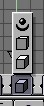
A 3DWindow offers 3 methods for 3D display:
Orthonormal. Blender offers this method from every view, not just from the X, Y or Z axes.
Perspective. You can toggle between orthonormal and perspective with the NUM5.
Camera. This is the view as rendered (NUM0).
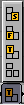
View Direction
These pre-sets can be used with either ortho or perspective. Respectively, these are the:
Top View, hotkey NUM7
Front View, hotkey NUM1
Right View, hotkey NUM3
Draw Mode
Set the drawing method. Respectively:
BoundBox. The quickest method, for animation previews, for example.
WireFrame.
Solid. Zbuffered with the standard OpenGL lighting. ZKEY toggles between WireFrame and Solid.
Shaded. This is as good an approach as is possible to the manner in which Blender renders - with Gouraud shading. It displays the situation from a single frame of the Camera. SHIFT+Z toggles, use CTRL+Z to force a recalculation.
Textured.

View Zoom
Move the mouse vertically to zoom in and out of the 3DWindow. This is an alternative for CTRL+MMB.

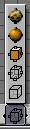
These buttons determine the manner in which the Objects (or vertices) are rotated or scaled.
Around Individual Centers
All Objects rotate or scale around their own midpoints. In EditMode: all vertices rotate or scale around the Object midpoint.

Proportional Vertex Editing Tool
The Proportional Editing tool can be activated, only in editmode, with the Icon in 3D window header, or OKEY. The Proportional Editing tool is then Available in Editmode for all Object types. This tool works like a 'magnet', you select a few vertices and while editing (grab, rotate, scale) the surrounding vertices move proportinal with it. Use NUM+ and NUM- keys or MW to adjust the area of influence, this can be done "live" while editing.

You can choose between a sharp fallof and a smooth falloff.
3DWindow
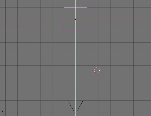
The standard 3DWindow has:
A grid. The dimensions (distance between the gridlines) and resolution (number of lines) can be set with the ViewButtons. This grid is drawn as infinite in the presets of ortho ViewMode (Top, Front, Right view). In the other views, there is an finite 'floor'. Many Blender commands are adjusted to the dimension of the grid, to function as a standard unit. Blender works best if the total 'world' in which the user operates continually falls more or less within the total grid floor (whether it is a space war or a logo animation).
Axes in colour codes. The reddish line is the X axis, the green line is the Y axis, the blue line is the Z axis. In the Blender universe, the 'floor' is normally formed by the X and Y axes. The height and 'depth' run along the Z axis.
A 3D cursor. This is drawn as a black cross with a red/white striped circle. A LeftMouse click moves the 3DCursor. Use the SnapMenu (SHIFT-S) to give the 3Dcursor a specific location. New Objects are placed at the 3D cursor location.
Layers (visible in the header buttons). Objects in 'hidden' layers are not displayed. All hotkey commands and tools in Blender take the layers into account: Objects in the 'hidden' layers are treated as not selected. See the following paragraph as well.
ViewButtons. Separate variables can be set for each 3Dwindow, e.g for the grid or the lens. Use the SHIFT-F7 hotkey or the WindowType button in the 3DHeader. The ViewButtons are explained in detail elsewhere in this manual.
The Mouse
The mouse provides the most direct access to the 3DWindow. Below is a complete overview:
Press LMB and drag
These are the Gestures. Blender's gesture recognition works in three ways:
Draw a straight line: start translation mode (Grabber)
Draw a curved line: start rotation mode.
Draw a V-shaped line: start scaling mode.
MMB
Rotate the direction of view of the 3DWindow. This can be done in two ways (can be set in the UserMenu):
the trackball method. In this case, where in the window you start the mouse movement is important. The rotation can be compared to rotating a ball, as if the mouse grasps and moves a tiny miniscule point on a ball and moves it. If the movement starts in the middle of the window, the view rotates along the horizontal and vertical window axes. If the movement begins at the edge of the window, the view rotates along the axis perpendicular to the window.
the turntable method. A horizontal mouse movement always results in a rotation around the global Z axis. Vertical mouse movements are corrected for the view direction, and result in a combination of (global) X and Y axis rotations.
RMB
Select Objects or (in EditMode) vertices. The last one selected is also the active one. This method guarantees that a maximum of 1 Object and 1 vertex are always selected. This selection is based on graphics (the wireframe).
SHIFT-RMB
Adds/removes from selection Objects or (in EditMode) vertices. The last one selected is also the active one. Multiple Objects or vertices may also be selected. This selection is based on graphics too (the wireframe).
CTRL-RMB
Select Objects on the Object-centers. Here the wireframe drawing is not taken into account. Use this method to select a number of identical Objects in succession, or to make them active.
NumPad
The numeric keypad on the keyboard is reserved for view related hotkeys. Below is a description of all the keys with a brief explanation.
NUM/
LocalView. The Objects selected when this command is invoked are taken separately and displayed completely, centered in the window. See the description of 3DHeader>>LocalView.
NUM*
Copy the rotation of the active Object to the current 3DWindow. Works as if this Object is the camera, without including the translation.
NUM.
Center and zoom in on the selected Objects. The view is changed in a way that can be compared to the LocalView option.
CTRL-NUM0
Make the active Object the camera. Any Object can be used as the camera. Generally, a Camera Object is used. It can also be handy to let a spotlight function temporarily as a camera when directing and adjusting it. ALT+NUM0 Revert to the previous camera. Only Camera Objects are candidates for 'previous camera'.
Hotkeys
This list contains all the hotkeys that can be used in a 3D window. EditMode hotkeys are described in the following paragraph.
PAGEUP
Select the next Object Key. If more than one Object Key is selected, the selection is shifted up cyclically. Only works if the AnimButtons->DrawKey is ON for the Object.
PAGEDOWN
Select the previous Object Key. If more than one Object Key is selected, the selection is shifted up cyclically. Only works if the AnimButtons->DrawKey is ON for the Object.
AKEY
Select All / deselect All. If any Object or vertex is selected, everthing is always deselected first.
SHIFT-A
This is the AddMenu. In fact, it is the ToolBox that starts with the 'ADD' option. When Objects are added, Blender starts EditMode immediately if possible.
CTRL-A
"Apply size/rot". The rotation and dimensions of the Object are assigned to the ObData (Mesh, Curve, etc.). At first glance, it appears as if nothing has changed, but this can have considerable consequences for animations or texture mapping. This is best illustrated by also having the axis of a Mesh Object be drawn (EditButtons->Axis). Rotate the Object and activate Apply. The rotation and dimensions of the Object are 'erased'.
CTRL-SHIFT-A
If the active Object is automatically duplicated (see AnimButtons->DupliFrames or AnimButtons->Dupliverts), a menu asks "Make dupli's real?". This option actually creates the Objects. If the active Mesh Object is deformed by a Lattice, a menu asks "Apply Lattice deform?". Now the deformation of the Lattice is assigned to the vertices of the Mesh.
BKEY
Border Select. Draw a rectangle with the LeftMouse; all Objects within this area are selected, but not made active. Draw a rectangle with the RightMouse to deselect Objects. In orthonormal ViewMode, the dimensions of the rectangle are displayed, expressed as global coordinates, as an extra feature in the lower left corner. In Camera ViewMode, the dimensions that are to be rendered according to the DisplayButtons are displayed in pixel units.
SHIFT-B
Render Border. This only works in Camera ViewMode. Draw a rectangle to render a smaller cut-out of the standard window frame. If the option DisplayButtons->Border is ON, a box is drawn with red and black lines.
SHIFT-C
CentreZero View. The 3DCursor is set to zero (0,0,0) and the view is changed so that all Objects, including the 3Dcursor, can be displayed. This is an alternative for HOME.
ALT-C
Convert Menu. Depending on the active Object, a PopupMenu is displayed. This enables you to convert certain types of ObData. It only converts in one direction, everything ultimately degrades to a Mesh! The options are:
"Font -> Curve"
"MetaBall -> Mesh" The original MetaBall remains unchanged.
"Curve -> Mesh"
"Surface -> Mesh"
CTRL-C
Copy Menu. This menu copies information from the active Object to (other) selected Objects.
Fixed components are:
"Copy Loc": the X,Y,Z location of the Object. If a Child is involved, this location is the relative position in relation to the Parent.
"Copy Rot": the X,Y,Z rotation of the Object.
"Copy Size": the X,Y,Z dimension of the Object.
"DrawType" : see EditButtons->DrawType.
"TimeOffs" : see AnimButtons->TimeOffs.
"Dupli": all Duplicator data from the AnimButtons
If applicable:
"Copy TexSpace": The texture space.
"Copy Particle Settings": the complete particle system from the AnimButtons.
For Curve Objects:
"Copy Bevel Settings": all beveling data from the EditButtons.
Font Objects:
"Copy Font Settings": font type, dimensions, spacing.
"Copy Bevel Settings": all beveling data from the EditButtons.
Camera Objects:
"Copy Lens": the lens value.
SHIFT-D
"Add Duplicate". The selected Objects are copied. The settings in the UserMenu (Duplication/Linking presets) determine what DataBlocks are also copied or are linked. Blender then automatically starts Grab Mode (GKEY).
ALT-D
"Add Linked Duplicate". The selected Objects are copied. The DataBlocks linked to Objects remain linked. Blender then automatically starts Grab Mode (GKEY).
CTRL-D
Draw the (texture) Image as wire. This option has a limited function. It can only be used for 2D compositing.
SHIFT-F
Fly Mode. Only from Camera ViewMode. The mouse cursor jumps to the middle of the window. It works as follows:
Mouse cursor movement indicates the view direction.
LMB (repeated): Fly faster.
MMB (repeated): Fly slower.
LMB and MMB toghether: Set speed to zero.
CTRL: translation downwards (negative Z).
ALT: translation upwards (positive Z).
ESC: Camera back to its starting position, terminate Fly Mode.
SPACE: Leave the Camera in current position, terminate Fly Mode.
CTRL-F
Sort Faces. The faces of the active Mesh Object are sorted, based on the current view in the 3DWindow. The leftmost face first, the rightmost last. The sequence of faces is important for the Build Effect (AnimButtons).
GKEY
Grab Mode. Or: the translation mode. This works on selected Objects and vertices. Blender calculates the quantity and direction of the translation, so that they correspond exactly � with the mouse movements, regardless of the ViewMode or view direction of the 3DWindow. Alternatives for starting this mode:
RMB
LMB to draw a straight line.
The following options are available in translation mode:
Limitors:
CTRL: in increments of 1 grid unit.
SHIFT: fine movements.
SHIFT-CTRL: in increments of 0.1 grid unit.
MMB togglse: A short click restricts the current translation to the X,Y or Z axis. Blender calculates which axis to use, depending on the already initiated mouse movement. Click MiddleMouse again to return to unlimited translation.
ARROWS: These keys can be used to move the mouse cursor exactly 1 pixel.
Grabber can be terminated with:
LMB SPACE or ENTER: move to a new position.
RMB or ESC: everything goes back to the old position.
Switching mode:
GKEY: starts Grab mode again.
SKEY: switches to Size mode.
RKEY: switches to Rotate mode.
IKEY
Insert Object Key. A keyposition is inserted in the current frame of all selected Objects. A PopupMenu asks what key position(s) must be added to the IpoCurves.
"Loc": The XYZ location of the Object.
"Rot": The XYZ rotation of the Object.
"Size": The XYZ dimensions of the Object
"LocRot": The XYZ location and XYZ rotation of the Object.
"LocRotSize": The XYZ location, XYZ rotation and XYZ dimensions of the Object.
"Layer": The layer of the Object.
"Avail": A position is only added to all the current IpoCurves, that is curves which already exists.
"Effector": (only for Ika Objects) the end-effector position is added.
"Mesh ", "Lattice ", "Curve" or "Surface": depending on the type of Object, a VertexKey can be added
CTRL-J
Join Objects. All selected Objects of the same type are added to the active Object. What actually happens here is that the ObData blocks are combined and all the selected Objects (except for the active one) are deleted. This is a rather complex operation, which can lead to confusing results, particularly when working with a lot of linked data, animation curves and hierarchies.
KKEY
Show (as) Keys. The DrawKey option is turned ON for all selected Objects. If all of them were already ON, they are all turned OFF. #->$11
SHIFT-K
A PopupMenu asks: "OK? Show and select all keys". The DrawKey option is turned ON for all selected Objects, and all Object-keys are selected. This function is used to enable transformation of the entire animation system.
SHIFT-L
Select Links menu. This menu enables you to select Objects that share links a DataBlock with the active Object. Use this function to obtain an overview of the sometimes quite complicated linked structures Blender can create.
"Object Ipo": all Objects with the same Object Ipo are selected.
"Object Data": all Objects with the same ObData (Mesh, Curve, etc.) are selected.
"Current Material": all Objects with the same active Material are selected (this is the Material in MaterialButtons).
"Current texture": all Objects with the same active Texture are selected (this is the Texture in MaterialButtons).
CTRL-L
Make Links menu. This menu is used to copy links between the active Object and selected Objects. Only the links (the references) are copied; the contents of the DataBlocks involved are not changed. The result of this operation is easy to see in the OopsWindow.
"To Scene": the selected Objects are also linked to another Scene. A second PopupMenu asks the user to specify a Scene. Objects that appear in more than one Scene are displayed with a blue null point.
"Object Ipo": all selected Objects are given a link to the Object Ipo of the active Object.
"Mesh data", "Curve data", "Font data", etc.: all selected Objects are given a link to the ObData of the active Object. Objects must be the same type!
"Materials": all selected Objects are given links that are identical to the Material(s) of the active Object. The entire Material situation is copied. If the active Object does not have any Materials, all Material links for the selected Objects are erased.
MKEY
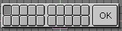
Move to Layer. This hotkey calls up a menu that can be used to view or change the layer settings of all the selected Objects. If the selected Objects have different layers, this is 'OR'ed in the menu display. Use ESC to exit the menu. Press the "OK" button or ENTER to change the layer seting. The hotkeys (ALT-)(1KEY, 2KEY, ... - 0KEY) work here as well (see 3DHeader).
NKEY
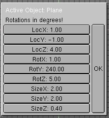
These buttons allow the user to enter numbers for the position, rotation and dimensions of the active Object. Use ESC to exit the menu without changing the Object. Press the "OK" button or ENTER to assign the changes to the Object.
ALT-O
Clear Origin. The 'Origin' is erased for all Child Objects, which causes the Child Objects to move to the exact location of the Parent Objects.
CTRL-P
Make Parent. The active Object becomes the Parent of the selected Objects. All transformations of the Parent are now passed on to the Children. This allows you to create complex hierarchies. As part of the 'Make Parent' operation, an inverse of the Parent transformation is calculated and stored in the Child Object. This inverse may make it seem as if all transformations remained unchanged after Make Parent was executed. Depending on the type of Object, special Parent relationships can be selected.
ALT-P
Clear Parent. All selected Child Objects are unlinked from the Parents. A PopupMenu asks you to make a selection:
"Clear Parent": the selected Child Objects are unlinked from the Parent. since the transformation of the Parent disappears, this can appear as if the former Children themselves are transformed.
"... and keep transform": the Child Objects are unlinked from the Parent, and an attempt is made to assign the current transformation, which was determined in part by the Parent, to the (former Child) Objects.
"Clear Parent inverse": The inverse matrix of the Parent of the selected Objects is erased. The Child Objects remain linked to the Objects. This gives the user complete control over the hierarchy.
RKEY
Rotate mode. Works on selected Objects and vertices. In Blender, a rotation is by default a rotation perpendicular to the screen, regardless of the view direction or ViewMode. The degree of rotation is exactly linked to the mouse movement. Try moving around the rotation midpoint with the mouse. The rotation midpoint is determined by the state of the 3DHeader->Around buttons.
XKEY , YKEY and ZKEY
While in rotation mode, these keys switch to a global axis rotation around the corresponding axis. Alternatives for starting rotation mode:
LMB (click-hold-draw): draw a C-shaped curve. The following options are available in rotation mode:
Limitors:
CTRL: in increments of 5 degrees.
SHIFT: finer control.
SHIFT-CTRL: finer control with increments of 1 degree.
MMB toggles the current rotation axis, which is perpendicular to the screen, with the two other axes, which are vertical and horizontal on the screen. The mouse movements here follow the two rotation axes. Click MiddleMouse again to return to a rotation axis perpendicular to the screen.
ARROWS: These keys move the mouse cursor exactly 1 pixel.
Switching mode:
RKEY: starts Rotate mode again.
SKEY: switches to Size mode.
GKEY: switches to Grab mode.
Rotation mode can be terminated with:
LMB SPACE ENTER: finalizes the rotation.
RMB or ESC: everything returns to the former state.
SKEY
Size mode or scaling mode. Works on selected Objects and vertices. The degree of scaling is exactly linked to the mouse movement. Try to move from the (rotation) midpoint with the mouse. The midpoint is determined by the settings of the 3DHeader->Around buttons. Alternatives for starting scaling mode:
LeftMouse (click-hold-draw) draw a V-shaped line.
The following options are available in scaling mode:
Limitors:
CTRL: in steps of 0.1.
SHIFT-CTRL: in steps of 0.01.
MMB restricts the scaling to the X, Y or Z axis. Blender calculates the appropriate axis based on the already initiated mouse movement. Click MiddleMouse again to return to free scaling.
ARROWS: These keys move the mouse cursor exactly 1 pixel.
XKEY Make the horizontal scaling negative; this is also called an X-flip.
YKEY Make the vertical scaling negative; this is also called a Y-flip.
Switching mode:
SKEY: starts Size mode again.
RKEY: switches to Rotate mode.
GKEY: switches to Grab mode.
LMB SPACE or ENTER: finalizes scaling.
RMB or ESC: everything returns to its previous state.
SHIFT-S
Snap Menu. This menu offers a number of options for precisely specifying the position of Objects or vertices.
"Sel -> Grid": all selected Objects or vertices are moved to the closest grid position.
"Sel -> Curs": all selected Objects or vertices are moved to the 3DCursor position.
"Curs -> Grid": the 3DCursor is moved to the closest grid position.
"Curs -> Sel": the 3DCursor is moved to the selected Object. If there are multiple Objects or vertices, the 3DCursor is set to the midpoint. The 3DHeader->Around buttons determine what type of midpoint is meant here.
TKEY
Texture space mode. The position and dimensions of the texture space for the selected Objects can be changed in the same manner as described above for Grab and Size mode. To make this visible, the drawingflag EditButtons->TexSpace is set ON. A PopupMenu asks you to select: "Grabber" or "Size".
CTRL-T
Make Track. All selected Objects are given a rotation constraint directed at the active Object. The type of rotation and which axis is up and which one is directed at the Track Object are specified in the AnimButtons.
ALT-T
Clear Track. The tracking is turned off for all selected Objects. A PopupMenu allows you to maintain the current tracking as the rotation in the Objects.
UKEY
Single User Menu. Use this menu to manage the (multi-) user structure. These operations only work on selected Objects and the DataBlocks that are linked to them.
"Object": if other Scenes also have a link to this Object, the link is deleted and the Object is copied. The Object now only exists in the current Scene. The links from the Object remain unchanged.
"Object & ObData": Similar to the previous command, but now the ObData blocks with multiple links are copied as well. All selected Objects are now present in the current Scene only, and each has a unique ObData (Mesh, Curve, etc.).
"Object & ObData & Materials+Tex": Similar to the previous command, but now Materials and Textures with multiple links are also copied. All selected Objects are now unique. They have unique ObData and each has a unique Material and Texture block.
"Materials+Tex": Only the Materials and Textures with multiple links are copied.
ALT-V
Object-Image Aspect. This hotkey sets the X and Y dimensions of the selected Objects in relation to the dimensions of the Image Texture they have. Use this hotkey when making 2D Image compositions and multi-plane designs to quickly place the Objects in the appropriate relationship with one another.
ALT-W
Write Videoscape. The selected Mesh Object is saved as an ASCII file. Use the FileWindow to enter a file name. Blender adds the extension ".obj" to the Videoscape file.
XKEY
Erase Selected. All selected Objects are deleted from the Scene and, if they are not linked to other Scenes, they are released. The ObData and other linked DataBlocks remain.